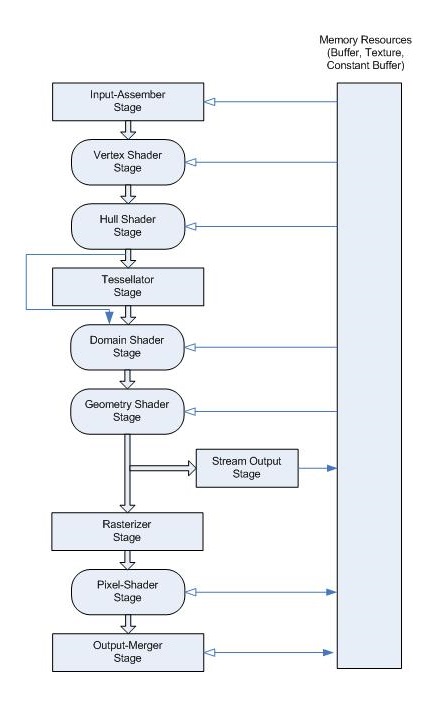
Graphics pipeline
The Direct3D graphics pipeline is designed for generating graphics for realtime gaming applications. Data flows from input to output through each of the configurable or programmable stages.
All of the stages can be configured using the Direct3D API. Stages that feature common shader cores (the rounded rectangular blocks) are programmable by using the HLSL programming language. This makes the pipeline extremely flexible and adaptable.
The most commonly used are the Vertex Shader (VS) stage and the Pixel Shader (PS) stage. If you don't provide even these shader stages, a default no-op, pass-through vertex and pixel shader are used.
Input Assembler stage
The Input Assembler (IA) stage supplies primitive and adjacency data to the pipeline, such as triangles, lines and points, including semantics IDs to help make shaders more efficient by reducing processing to primitives that haven't already been processed.
Input
Primitive data (triangles, lines, and/or points), from user-filled buffers in memory. And possibly adjacency data. A triangle would be 3 vertices for each triangle and possibly 3 vertices for adjacency data per triangle.
Output
Primitives with attached system-generated values (such as a primitive ID, an instance ID, or a vertex ID).
Vertex Shader stage
The Vertex Shader (VS) stage processes vertices, typically performing operations such as transformations, skinning, and lighting. A vertex shader takes a single input vertex and produces a single output vertex. Individual per-vertex operations, such as Transformations, Skinning, Morphing and Per-vertex lighting.
Input
A single vertex, with VertexID and InstanceID system-generated values. Each vertex shader input vertex can be comprised of up to 16 32-bit vectors (up to 4 components each).
Output
A single vertex. Each output vertex can be comprised of as many as 16 32-bit 4-component vectors.
Hull Shader stage
The Hull Shader (HS) stage is one of the tessellation stages, which efficiently break up a single surface of a model into many triangles. A hull shader is invoked once per patch, and it transforms input control points that define a low-order surface into control points that make up a patch. It also does some per-patch calculations to provide data for the Tessellator (TS) stage and the Domain Shader (DS) stage.
Input
Between 1 and 32 input control points, which together define a low-order surface.
Output
Between 1 and 32 output control points, which together make up a patch. The hull shader declares the state for the Tessellator (TS) stage, including the number of control points, the type of patch face, and the type of partitioning to use when tessellating.
Tessellator stage
The Tessellator (TS) stage creates a sampling pattern of the domain that represents the geometry patch and generates a set of smaller objects (triangles, points, or lines) that connect these samples.
Input
The tessellator operates once per patch using the tessellation factors (which specify how finely the domain will be tessellated) and the type of partitioning (which specifies the algorithm used to slice up a patch) that are passed in from the hull-shader stage.
Output
The tessellator outputs uv (and optionally w) coordinates and the surface topology to the domain-shader stage.
Domain Shader stage
The Domain Shader (DS) stage calculates the vertex position of a subdivided point in the output patch; it calculates the vertex position that corresponds to each domain sample. A domain shader is run once per tessellator stage output point and has read-only access to the hull shader output patch and output patch constants, and the tessellator stage output UV coordinates.
Input
A domain shader consumes output control points from the Hull Shader (HS) stage. The hull shader outputs include: Control points, Patch constant data, and Tessellation factors (the tessellation factors can include the values used by the fixed-function tessellator as well as the raw values - before rounding by integer tessellation - which facilitates geomorphing, for example). A domain shader is invoked once per output coordinate from the Tessellator (TS) stage.
Output
The Domain Shader (DS) stage outputs the vertex position of a subdivided point in the output patch.
Geometry Shader stage
The Geometry Shader (GS) stage processes entire primitives: triangles, lines, and points, along with their adjacent vertices. It supports geometry amplification and de-amplification. It is useful for algorithms including Point Sprite Expansion, Dynamic Particle Systems, Fur/Fin Generation, Shadow Volume Generation, Single Pass Render-to-Cubemap, Per-Primitive Material Swapping, and Per-Primitive Material Setup - including generation of barycentric coordinates as primitive data so that a pixel shader can perform custom attribute interpolation.
Input
Unlike vertex shaders, which operate on a single vertex, the geometry shader's inputs are the vertices for a full primitive (three vertices for triangles, two vertices for lines, or single vertex for point).
Output
The Geometry Shader (GS) stage is capable of outputting multiple vertices forming a single selected topology. Available geometry shader output topologies are tristrip, linestrip, and pointlist. The number of primitives emitted can vary freely within any invocation of the geometry shader, though the maximum number of vertices that could be emitted must be declared statically. Strip lengths emitted from a geometry shader invocation can be arbitrary, and new strips can be created via the RestartStrip HLSL function.
Stream Output stage
The Stream Output (SO) stage continuously outputs (or streams) vertex data from the previous active stage to one or more buffers in memory. Data streamed out to memory can be recirculated back into the pipeline as input data, or read-back from the CPU.
Input
Vertex data from a previous pipeline stage.
Output
The Stream Output (SO) stage continuously outputs (or streams) vertex data from the previous active stage, such as the Geometry Shader (GS) stage, to one or more buffers in memory. If the Geometry Shader (GS) stage is inactive, and the Stream Output (SO) stage is active, it continuously outputs vertex data from the Domain Shader (DS) stage to buffers in memory (or if the DS is also inactive, from the Vertex Shader (VS) stage).
Rasterizer stage
The Rasterizer (RS) stage clips primitives that aren't in view, prepares primitives for the Pixel Shader (PS) stage, and determines how to invoke pixel shaders. Converts vector information (composed of shapes or primitives) into a raster image (composed of pixels) for the purpose of displaying real-time 3D graphics.
Input
Vertices (x,y,z,w) coming into the Rasterizer stage are assumed to be in homogeneous clip-space. In this coordinate space the X axis points right, Y points up and Z points away from camera.
Output
The actual pixels that need to be rendered. Includes some vertex attributes for use in interpolation by the Pixel Shader.
Pixel Shader stage
The Pixel Shader (PS) stage receives interpolated data for a primitive and generates per-pixel data such as color.
Input
When the pipeline is configured without a geometry shader, a pixel shader is limited to 16, 32-bit, 4-component inputs. Otherwise, a pixel shader can take up to 32, 32-bit, 4-component inputs. Pixel shader input data includes vertex attributes (that can be interpolated with or without perspective correction) or can be treated as per-primitive constants. Pixel shader inputs are interpolated from the vertex attributes of the primitive being rasterized, based on the interpolation mode declared. If a primitive gets clipped before rasterization, the interpolation mode is honored during the clipping process as well.
Output
A pixel shader can output up to 8, 32-bit, 4-component colors, or no color if the pixel is discarded. Pixel shader output register components must be declared before they can be used; each register is allowed a distinct output-write mask.
Output Merger stage
The Output Merger (OM) stage combines various types of output data (pixel shader values, depth and stencil information) with the contents of the render target and depth/stencil buffers to generate the final pipeline result.
Input
Output Merger inputs are the Pipeline state, the pixel data generated by the pixel shaders, the contents of the render targets and the contents of the depth/stencil buffers.
Output
The final rendered pixel color.
Related topics
Feedback
Coming soon: Throughout 2024 we will be phasing out GitHub Issues as the feedback mechanism for content and replacing it with a new feedback system. For more information see: https://aka.ms/ContentUserFeedback.
Submit and view feedback for