Connections Between Two Unit Plugs in Different AV/C Units
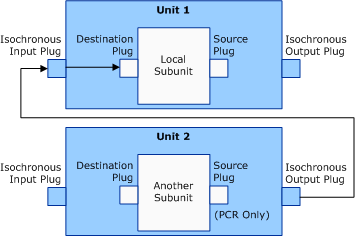
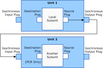
Scenarios 7 and 8 represent connections between a subunit in one unit to a subunit in a different unit, where the target does not support subunit to unit connections within one AV/C unit. These type of connections require the Signal source and Input select CCM commands.
Scenarios 7 and 8 describe subunit source or destination plugs that have the KSPIN_FLAG_AVC_PCRONLY flag set in the Flag member of their AVCPRECONNECTINFO structures, which is translated by Avc.sys to 0xFF for their subunit's address.
Scenario 7
Signal source: Intra-unit connection is not supported by the local unit.
Input select: The local unit connects from any available (0x7F) isochronous output plug on the target unit to any available (0x7F) isochronous input plug on the local unit and then connects to a specific (0x0 to 0x1E) or any available (0xFF) subunit destination plug on the local unit.

Scenario 7 describes a connection where the local pin's DataFlow member is KSPIN_DATAFLOW_IN.
Each column in the following table corresponds to a member of the AVCCONNECTINFO structure and specifies values for these members for a source subunit plug.
| DeviceID | SubunitAddress | SubunitPlugNumber | UnitPlugNumber (for isochronous output) |
|---|---|---|---|
Target |
Subunit address |
Source plug (0xFF) - value is ignored |
0x0 to 0x1E, or 0xFF |
Each column in the following table corresponds to a member of the AVCCONNECTINFO structure and specifies values for these members for a destination subunit plug.
| DeviceID | SubunitAddress | SubunitPlugNumber | UnitPlugNumber (for isochronous input) |
|---|---|---|---|
Self |
Self |
Destination plug (0x0 to 0x1E, or 0xFF) |
0x7F |
Scenario 8
Signal source: The local unit connects to any subunit's source plug to any available (0x7F) isochronous output plug (and returns the isochronous output plug's number).
Input select: The target unit connects from local unit's isochronous output plug (returned in signal source CCM command) to any available (0x7F) isochronous input plug on the target unit.

Scenario 8 describes a connection where the local pin's DataFlow member is KSPIN_DATAFLOW_OUT.
Each column in the following table corresponds to a member of the AVCCONNECTINFO structure and specifies values for these members for a source subunit plug.
| DeviceID | SubunitAddress | SubunitPlugNumber | UnitPlugNumber (for isochronous output) |
|---|---|---|---|
Self |
Self |
Source plug (0x0 to 0x1E, or 0xFF) |
0x7F |
Each column in the following table corresponds to a member of the AVCCONNECTINFO structure and specifies values for these members for a destination subunit plug.
| DeviceID | SubunitAddress | SubunitPlugNumber | UnitPlugNumber (for isochronous input) |
|---|---|---|---|
Target |
Subunit Address |
Destination plug (0xFF) - value is ignored |
0x0 to 0x1E, or 0x7F |
The following list describes the meaning of values that appear in the preceding tables:
The values 0x0 to 0x1E (30 decimal) represent specific plug numbers.
The value 0x7F represents any available isochronous input or output plug number on the AV/C unit.
The value 0xFF represents any available subunit source or destination plug address.
"Self" contains the pin to which the AVCCONNECTINFO structure is setting. "Target" represents the data that the AVCCONNECTINFO structure is for.
The values in the DeviceID columns (for source and destination subunit plugs) are used to search for the physical device object (PDO) of the target AV/C device to issue AV/C CCM commands to.
Feedback
Coming soon: Throughout 2024 we will be phasing out GitHub Issues as the feedback mechanism for content and replacing it with a new feedback system. For more information see: https://aka.ms/ContentUserFeedback.
Submit and view feedback for